1 Introduction
Since the Industrial Revolution, human demand for renewable energy has continued to grow. With the increasing awareness of environmental protection, wind energy, as a clean and renewable energy source, has been widely adopted [1, 2]. Offshore wind power, with its stable wind speeds, vast sea surfaces, low noise levels, and avoidance of land constraints, is emerging as a key component of future renewable energy [3, 4]. Compared to onshore wind power, offshore wind speeds are higher and wind directions more stable, providing superior wind energy resources that enhance power generation efficiency; power generation produces less noise, with high and stable output, reducing generation costs; and as technology continues to advance, the economic viability of offshore wind power is increasingly evident, offering broader development prospects [5, 6, 7, 8]. By the end of 2024, the global cumulative installed capacity of offshore wind power will reach 86 GW, with an additional 4.04 GW installed in 2020.
Offshore wind power infrastructure offers significant advantages for the entire world [9]. It can be said that in the coming years, the construction of offshore wind power will be one of the top priorities for countries worldwide. Among these, the stability and reliability of offshore wind power foundation structures are particularly important for ensuring the long-term safe and stable operation of wind farms and guaranteeing economic benefits. These engineering facilities support the stable operation of offshore wind power [10, 11]. The foundation structures for offshore wind power are categorized into pile foundation structures, gravity foundation structures, negative pressure bucket foundation structures, floating foundation structures, and jacket foundation structures [12, 13, 14]. The tidal zone is located between the average high tide level and the average low tide level. Due to water level fluctuations, alternating wet and dry conditions, and biological erosion, materials in this zone are subject to corrosion, wear, and their coupled effects, leading to the destruction of facilities [15, 16]. This zone is the most severely affected by corrosion and wear in offshore wind turbine foundation structures, making the coating of infrastructure in this zone particularly important. The failure of this coating can result in maintenance costs exceeding 35% [17, 18]. During the process of erosion and wear of the soil surrounding the foundation, the bearing capacity of the foundation undergoes changes; simultaneously, the horizontal bearing capacity of the foundation decreases as erosion pits and wear areas expand. Once the foundation’s bearing capacity becomes insufficient to support the normal operation of the offshore wind power foundation structure due to the continuous expansion of erosion pits and wear areas, the entire offshore wind power foundation structure may experience instability or other accidents, resulting in significant economic losses [19, 20, 21, 22, 23]. Therefore, the erosion and wear resistance performance of coatings on offshore wind turbine foundation structures in tidal zones has garnered significant attention.
For wear-resistant and erosion-resistant coating materials, epoxy coal tar coatings were used in the early stages, but their wear resistance decreased after a period of service [24]. Ghosh et al. [25] reported that tar-free quartz epoxy amine coatings exhibit good wear resistance, and tar-free nano-filler-based epoxy coatings demonstrate even better wear resistance. Therefore, many researchers have applied nanomaterials in the preparation of coatings. In tests conducted by Frost-Jensen et al. [26] on the erosion resistance of wind turbine blade surfaces, polymer coatings containing graphene and mixed nano-reinforced materials improved the erosion resistance and service life of the original coatings. Momber et al. [27] noted that the abrasion resistance of organic coatings on offshore wind power structures varies with different polymer hardness levels, with epoxy resin \(\mathrm{>}\) polysiloxane \(\mathrm{>}\) polyurethane. Zhang et al. [28] developed an epoxy resin coating material modified with boron-nitrogen-silicon carbide. Compared to conventional coatings without fillers, this coating reduces the coefficient of friction and also possesses corrosion resistance and hydrophobic properties. Chen et al. [29] utilized the properties of nano-cerium oxide and polytetrafluoroethylene to design a multifunctional composite coating with excellent corrosion resistance and wear resistance for aluminum alloys. Compared to phenolic epoxy coatings, this coating exhibits a 6.8-fold improvement in wear resistance. Zhang et al. [30] modified the performance of glass flakes using 3-triethoxysilylpropylamine, obtaining glass flake composite materials containing phytate and zinc ions. These were added to water-based epoxy coatings, significantly enhancing both the abrasion resistance and corrosion resistance of the water-based epoxy coatings.
This paper first briefly analyzes the structural composition of offshore wind turbine equipment, with a focus on the corrosion conditions of the wind tower foundation and tower cylinder. Based on the surface characteristics of different regions of the offshore wind turbine foundation caisson and the requirements of the coating system, a corrosion protection coating scheme is proposed. Additionally, the testing methods and evaluation criteria for coating thickness, adhesion, corrosion resistance, and erosion wear performance are sequentially described. Second, acrylic polymers are prepared as corrosion-resistant coating materials, and the addition ratio of the corrosion-resistant coating is determined through impact resistance and seawater contact angle characterization. Furthermore, an anti-erosion wear coating is prepared using WC-Co hard alloy, and the coating’s X-ray diffraction and microstructure are analyzed. Finally, epoxy resin is selected as the repair material for the wear-prone areas of offshore wind turbine foundations, and its basic mechanical properties under laser cladding technology are explored. A sand-water jet erosion test is conducted to evaluate the erosion resistance of the cladding layer.
2 Offshore wind turbine structure
The structural components of offshore wind turbines primarily consist of the foundation, tower, nacelle, hub, blades, and various mechanical and electrical components within the nacelle. The foundation and tower are located in a more complex environment, encompassing all the aforementioned areas, while the remaining components are situated in the marine atmospheric zone. The corrosion conditions of the foundation and tower are discussed separately as follows:
The foundation types for offshore wind turbine units primarily include gravity foundations, suction pile foundations, floating foundations, and pile foundations. Among these, pile foundations can be further classified into single-pile foundations, three-pile foundations, jacket foundations, and multi-pile foundations. Gravity foundations primarily rely on their own weight to keep the wind turbine vertically upright on the sea surface, typically constructed as reinforced concrete caisson structures. Suction pile foundations, also known as suction-type foundations, are cylindrical structures with an open bottom and no upper closure. They are driven into the seabed to a certain depth using their own weight, then water is extracted through pre-drilled drainage holes in the top cover to create a negative pressure inside the cylinder. The pressure difference forces the foundation into the seabed to the desired depth. Floating foundations are box-shaped platforms that float on the sea surface, anchored to the seabed using an anchoring system. Pile foundations consist of piles and upper caissons (including concrete caissons and steel caissons), which can be fixed using methods such as pile driving, drilling, and casting. A jacket foundation is a steel conical spatial frame with steel pipes as its structural members. It is welded on land, transported to the installation site, and positioned, with steel piles driven into the seabed through the jacket. Therefore, the primary structural materials for offshore wind turbine foundations are steel or reinforced concrete.
3 Design of coating systems
3.1 Coating system design
Based on the design service life and environmental conditions of the concrete foundations for current offshore wind turbine prototypes, this paper combines relevant technical specifications for corrosion protection of concrete structures in port engineering and design coating system requirements from technical specifications for corrosion protection of offshore wind turbine units to implement the following corrosion protection coating scheme:
For embedded anchor bolts, a composite corrosion protection scheme using Dacromet + epoxy thick-film paint + PVC sleeves + bolt protection covers is adopted.
For the contact surfaces between the concrete foundation caisson and dry-laid stone blocks, a “base coat + top coat” coating system is used. The base coat employs epoxy concrete sealer paint, with paint model number 05990-00000 and a dry film thickness of 60 \(\mu\)m. The top coat uses epoxy asphalt paint, with paint model number 15130-19990 and a dry film thickness of 555 \(\mu\)m. Therefore, the total dry film thickness of the coating on the bottom of the foundation cap is 615 \(\mu\)m.
The upper surface and vertical surfaces of the concrete foundation cap use a “base coat + intermediate coat + top coat” coating system. The base coat uses an epoxy concrete sealer, paint model 05990-00000, with a dry film thickness of 60 \(\mu\)m. The intermediate layer uses an epoxy glass flake thick coating, with the coating model number 35870-19990, and a dry film thickness of 455 \(\mu\)m. The top layer uses an acrylic polyurethane topcoat, with the coating model number 55210-47290, and a dry film thickness of 85 \(\mu\)m. Therefore, the total dry film thickness of the coating on the outer surface of the pile cap is 600 \(\mu\)m.
3.2 Coating system characterization methods
3.2.1 Thickness inspection
Methods for testing the thickness of anti-corrosion coatings include mechanical thickness measurement, optical thickness measurement, magnetic thickness measurement, and ultrasonic thickness measurement. This test uses magnetic thickness measurement, employing a 2812 magnetic film thickness tester for inter-process inspection and finished product film thickness inspection.
3.2.2 Bond strength testing
The main methods for testing the adhesion of anti-corrosion coatings include the paint film circle test, the paint film grid test, and the paint film peel test. This paper uses a multi-layer sprayed anti-corrosion coating, and the adhesion test employs the paint film peel test method, utilizing the PosiTest AT-M adhesion tester. Testing is conducted after the relevant coating application processes are completed, with the requirement that the coating adhesion be no less than 6 MPa.
3.2.3 Corrosion resistance testing
1) Neutral salt spray test. The neutral salt spray test is conducted after the coating process is completed. The test conditions are as follows: the temperature of the salt spray chamber is (36\(\mathrm{\pm}\)3)\(\mathrm{{}^\circ}\)C, the concentration of the sodium chloride solution is (55\(\mathrm{\pm}\)15) g/L, and the pH value is 6.6–7.3. The average collection rate of the salt spray solution measured over a minimum cycle of 24 hours on a salt spray collector with an area of 85 cm\(^2\) should be 1.23–2.17 mL/h, and the sprayed test solution cannot be reused. This test is conducted in a salt spray corrosion test chamber that meets the specified conditions. Evaluation criteria: When the design service life of the coating exceeds 30 years, the test duration should be no less than 2,500 hours, with no rust, bubbles, cracks, or peeling, and only minor discoloration and loss of gloss are permitted.
2) Humidity and heat test. The humidity and heat test is conducted after the spraying process is completed, under the following test conditions: alternating air humidity and air temperature, i.e., 8.5 hours of heating at a temperature of (41 \(\mathrm{\pm}\) 2.5)\(\mathrm{{}^\circ}\)C and relative humidity of 95.50% to 100%. 15 hours of cooling at a temperature of 20–30\(\mathrm{{}^\circ}\)C and relative humidity of 40%–50%. The test is conducted in a rust-preventive oil damp heat test chamber that meets the specified conditions. Evaluation criteria: When the designed service life of the coating is greater than 30 years, the test duration must be no less than 2,500 hours, with no rust, bubbles, cracks, or peeling. Slight discoloration (Grade 2) and loss of gloss (Grade 2) are permitted.
3.2.4 Scouring wear performance test
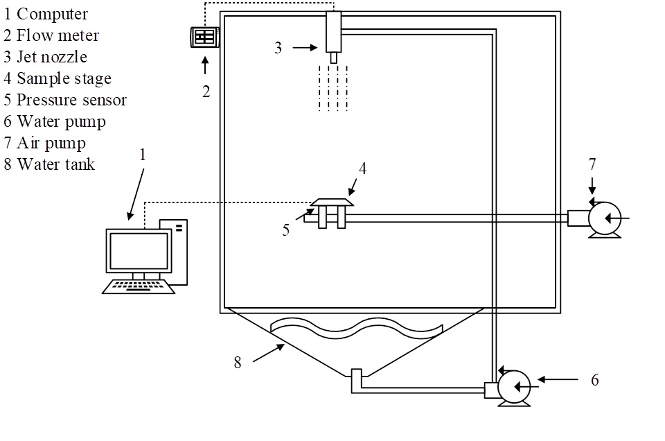
This paper employs the jet impact method to test the erosion resistance of various samples. The jet impact method is widely used to study the erosion corrosion behavior of materials under the impact of two-phase flow (solid-liquid). The upper surface of the coating is selected as the erosion wear test surface. The erosion samples are cut from the substrate using an electric spark cutting machine, with dimensions of 25mm \(\mathrm{\times}\) 30mm \(\mathrm{\times}\) 15mm. The sample surfaces are pre-ground using a grinding machine, Then, the test surface was ground to 1500 grit and polished using metallographic sandpaper. After polishing, the samples were placed in anhydrous ethanol for 12 minutes of ultrasonic cleaning, rinsed with deionized water, and dried to remove any impurities adhering to the surface of the erosion samples. After cleaning, the mass of the samples was weighed using an electronic balance with a precision of 0.1 mg. After completing the above preparatory work, the erosion wear test is initiated. Each sample undergoes a total erosion time of 60 minutes, with the sample removed every 20 minutes for cleaning and weighing until the erosion test is completed. The erosion wear performance test parameters are as follows: Flow rate: 25 L/min, erosion distance: 355 mm, erosion angle: 90/30\(\mathrm{{}^\circ}\), erosion exposure increment: 20 minutes, total erosion time: 90 minutes, erosion particles: SiQ2, erosion particle size: 300–500 \(\mu\)m, erosion particle concentration: 6 wt.%. The erosion wear testing equipment is shown in Figure 1.
4 Optimization of the abrasion resistance of coating systems
This section focuses on the application overview, preparation, and performance testing of the topcoat coatings (acrylic polyurethane topcoat, epoxy asphalt paint) used for the different orientations of the offshore wind turbine foundation caissons mentioned earlier. Additionally, WC-Co hard alloy is prepared as an anti-abrasion wear coating, and its X-ray diffraction and microstructure are analyzed through X-ray and microscopic observation.
4.1 Preparation and testing of bio-based anti-corrosion coatings
This paper uses acrylic resin as raw material and employs chemical modification methods to synthesize acrylic polymers with high solid content and excellent coating properties. These polymers are incorporated into the topcoat of the foundation of an offshore wind turbine prototype, resulting in a new type of marine anti-corrosion coating. To determine the optimal addition ratio of the acrylic polymer in the coating, this section simulates the experimental environment of the marine tidal zone and sequentially conducts impact resistance, pencil hardness, and contact angle tests on the coating.
4.1.1 Impact resistance characterization
Impact resistance measures a coating’s ability to withstand rapid deformation from a heavy blow without cracking, wrinkling, or peeling. In tidal marine environments, coatings with poor impact resistance can expose metal substrates and accelerate corrosion. In this study, paint films with varying acrylic polymer content (8%, 13%, 18%, and 23%) were tested (see Table 1: A \(=\) cracks, B \(=\) wrinkles, C \(=\) no damage). At 8% acrylic polymer and a 70 cm impact height, cracks appeared; at 13% and 80 cm, wrinkles formed. With 18% or higher acrylic content and 90 cm or greater, no defects were observed. Thus, increasing the acrylic polymer mass fraction enhances both the impact resistance and flexibility of the coating. When the mass fraction exceeds 18%, the film’s resistance surpasses the measurement upper limit (100 cm), greatly exceeding the required standard of 50 cm.
| \(\omega\)(%) | Impact height(cm) | Phenomenon of destruction |
|---|---|---|
| 8 | 70 | A |
| 13 | 80 | B |
| 18 | 90 | C |
| 23 | 100 | C |
4.1.2 Pencil hardness characterization
The hardness of a coating can be characterized by the hardness of a specific pencil, which measures the ability of the paint film surface to resist indentation deformation and scratching under external force. In this study, pencil hardness characterization experiments were conducted to test the pencil hardness of paint films with different mass fractions. The results are shown in Table 2. According to current relevant standards, pencil hardness is indicated by the highest hardness pencil that did not cause damage.
When the mass fraction of acrylic polymer is 8%, the pencil hardness of the paint film is 3H. When the mass fraction of acrylic polymer is increased to 13%, although the pencil hardness of the paint film remains 3H, the hardness of the paint film has improved, as evidenced by the change in damage phenomena from abrasion to scratching. Comparing the test results for acrylic polymer concentrations of 13% and 18%, the pencil hardness increases from 3H to 4H in the same manner. As the acrylic polymer content increases, the number of rigid large rings grafted into the branched structure of the coating gradually increases, thereby enhancing the system’s hardness. However, even when the acrylic polymer content is further increased to 23%, the paint film hardness does not show a significant change. This indicates that the acrylic polymer can to some extent resist the rigidity changes caused by the increase in large rings.
| \(\omega\)(%) | Hardness grade (H) | Phenomenon of destruction |
|---|---|---|
| 8 | 3 | No damage within 3 H and scratches within 4 H |
| 13 | 3 | No damage within 3 H and no scratches within 4 H |
| 18 | 4 | No damage within 4 H and no scratches within 5 H |
| 23 | 4 | No damage within 4 H and no scratches within 5 H |
4.1.3 Characterization of seawater contact angle
Due to tidal fluctuations, marine equipment steel structures are frequently exposed to alternating dry and wet conditions. Therefore, in addition to possessing adequate stain resistance, the paint film must also exhibit sufficient seawater resistance. The contact angle is closely related to the paint film’s stain resistance and water resistance, serving as a key parameter for evaluating the surface hydrophilicity/hydrophobicity of the paint film. Currently, it is believed that when the contact angle \(\theta\) \(\mathrm{>}\) 90\(\mathrm{{}^\circ}\), the paint film has a hydrophobic structure, and the larger the contact angle, the better the hydrophobic performance. When the contact angle \(\theta\) \(\mathrm{<}\) 90\(\mathrm{{}^\circ}\), the paint film has a hydrophilic structure, and the smaller the contact angle, the better the hydrophilic performance. The test results for seawater resistance contact angles of paint films at different mass fractions are shown in Table 3.
| \(\omega\)(%) | \(\theta\)(\(\mathrm{{}^\circ}\)) |
|---|---|
| 8 | 87.72 |
| 13 | 89.71 |
| 18 | 92.45 |
| 23 | 91.79 |
As the mass fraction of acrylic polymers increases, the hydrophobicity of the paint film surface gradually increases. When the mass fraction of acrylic polymers reaches 18%, the paint film becomes a hydrophobic material (\(\theta\) = 92.45\(\mathrm{{}^\circ}\)), possibly due to the large ring molecular structure, which plays a hydrophobic role and reduces affinity with water. When the mass fraction of acrylic polymer reaches 23%, the contact angle of the paint film decreases (\(\theta\) = 91.79\(\mathrm{{}^\circ}\)), and the hydrophobic performance declines. This may be due to a decrease in the crosslinking degree of the paint film, resulting in insufficiently dense film formation on the surface.
Based on the above analysis, it can be concluded that moderately increasing the addition ratio of acrylic polymer can significantly enhance the paint film’s flexibility, pencil hardness, and hydrophobic properties. There is no significant difference in performance between paint films containing 23% and 18% acrylic polymer by mass fraction. Considering cost control, the optimal addition ratio recommended in this study is 18%.
4.2 Preparation and inspection of anti-erosion wear coatings
WC-Co cemented carbide possesses high hardness, high strength, and excellent wear resistance, enabling it to effectively withstand erosion and wear in marine environments. However, the material is scarce and expensive. Therefore, this paper selects the atmospheric plasma spraying method to prepare WC-Co composite coatings on the steel substrates of offshore wind power equipment. In this section, an X-ray diffractometer (XRD) and an energy dispersive spectrometer are used to analyze the phase composition and composition of the coating.
4.2.1 Coating X-ray diffraction analysis
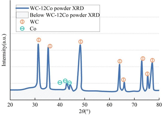
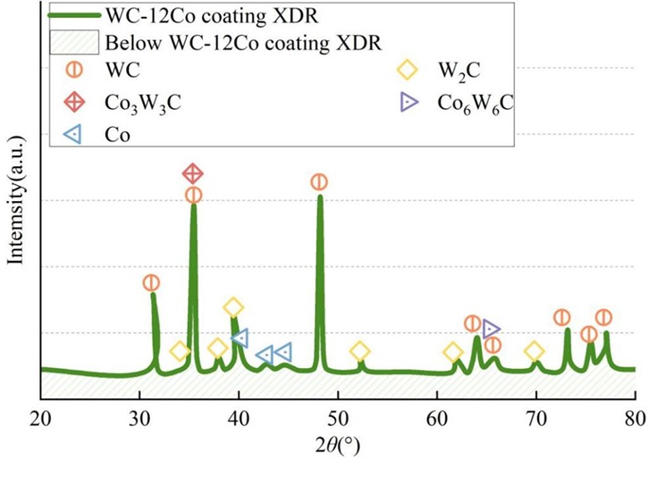
The XRD patterns of the original WC-Co powder are shown in Figure 2, and those of the WC-12Co coating are shown in Figure 3. Comparing Figures 2 and 3, it can be seen that in the WC-12Co coating, in addition to the WC phase, some W\(_2\)C and Co\(_3\)W\(_3\)C phases are formed, along with a small amount of Co\(_6\)W\(_6\)C phase. In the coating, the Co peak (2\(\theta\) = 45.23\(\mathrm{{}^\circ}\), d = 0.211 nm) exhibits a leftward shift and varying degrees of broadening, indicating that during the flight process, some WC decomposes into W atoms and C atoms that dissolve into the Co, preventing the atoms from precipitating in time. This forms a solid solution, increasing the interplanar spacing and causing the peak position to shift. The decomposition and oxidation of WC significantly affect the coating properties. Mild decarburization of WC only produces the W\(_2\)C phase, while severe decarburization results in elemental W. Under these parameters, no elemental W was detected, and only trace amounts of Co\(_3\)W\(_3\)C and Co\(_6\)W\(_6\)C amorphous phases were observed.
4.2.2 Microscopic analysis of coating cross-section
Microscopic observation reveals distinct layering between the substrate, bonding layer, and coating in the cross-sectional morphology of the coating. The WC-12Co coating has a thickness of approximately 350 \(\mu\)m, followed by the bonding layer with a thickness of approximately 50 \(\mu\)m. The interface boundary is flat with some undulations, having a thickness of approximately 100 \(\mu\)m, forming a sawtooth-like interlocking phenomenon. The element distribution at the coating cross-section is shown in Figure 4.
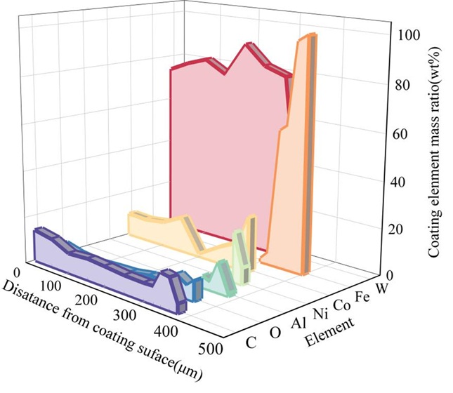
Within a distance of approximately 300 \(\mu\)m, the content (mass fraction) of C and Co fluctuates around 10.18%. The coating contains a relatively high amount of W, and trace amounts of Fe are present within the range of 51.99% to 88.97%, with a content of only 0.87%. As the distance increases, the W element disappears, and the Fe content continues to increase, reaching 95.91% at approximately 383 \(\mu\)m, and then increasing to 100% as the distance further increases, reaching the interior of the substrate. At approximately 300 \(\mu\)m, Al content 4.76%) appears. As the distance increases, its content first increases, then decreases, and gradually disappears. At approximately 380 \(\mu\)m, the Al content is only 0.83%, while Ni fluctuates in between.
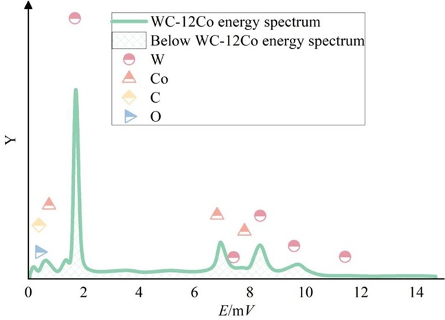
Based on the above analysis, it can be inferred that metallic elements W, Co, Fe, Ni, and Al, as well as non-metallic element C, exhibit varying degrees of diffusion. There exists a certain degree of metallurgical bonding between the matrix, bonding layer, and coating. The EDS analysis of the cross-section of the WC-12Co coating is shown in Table 4, and the energy spectrum is shown in Figure 5. In this region, the mass fraction of Co is 18.22%, with only W, C, and Co elements present, and the coating structure is unevenly distributed. The metallic Co plays a role in wetting the WC and its surrounding cobalt-based alloy crystalline phases, improving the bonding state between the WC and its surrounding metallic crystalline phases, thereby enhancing the coating’s resistance to erosion and wear.
| Element | Mass fraction(%) | Action fraction(%) |
|---|---|---|
| CK | 15.12 | 52.14 |
| OK | 9.44 | 23.41 |
| CoK | 18.22 | 14.53 |
| WK | 64.79 | 17.5 |
| Total | 100.00 | 100.00 |
4.3 Matrix repair based on laser cladding technology
The steel currently used in offshore wind power equipment is primarily martensitic stainless steel. The contact surfaces between the foundation caissons and dry-laid stone blocks are prone to pitting defects and cracking in marine tidal environments. This paper proposes laser cladding technology as a repair method for critical components/areas of offshore wind turbine equipment. To enhance the base material’s resistance to erosion and wear, epoxy resin is selected as the cladding material, with coal tar asphalt as the binder, to prepare an epoxy asphalt coating. This section explores the basic mechanical properties of the epoxy resin asphalt coating and analyzes the erosion and wear resistance of the cladding layer.
4.3.1 Basic mechanical properties of epoxy resin asphalt coating
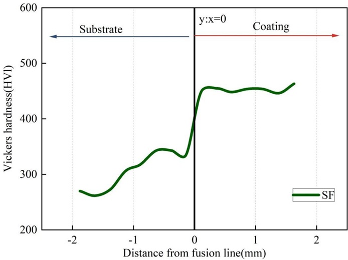
The results of microhardness testing on the cross-section of the cladding layer are shown in Figure 6. Each hardness value represents the average of five tests, and to avoid mutual interference, each hardness point is spaced 0.2 \(\mu\)m apart. The line y:x=0 represents the fusion line. It can be observed that, compared to the base material section, the hardness values in the cladding layer exhibit smaller variations, and the hardness at the top of the cladding layer (460.03 HVl) is significantly higher than that at the middle and bottom sections. In the base material section, the hardness values gradually decrease toward the direction away from the fusion line, reaching the martensitic stainless steel base material hardness of 276.25 HVl. The maximum hardness in the heat-affected zone reached 343.16 HVl, indicating that the heat-affected zone underwent some strengthening during the laser cladding process.
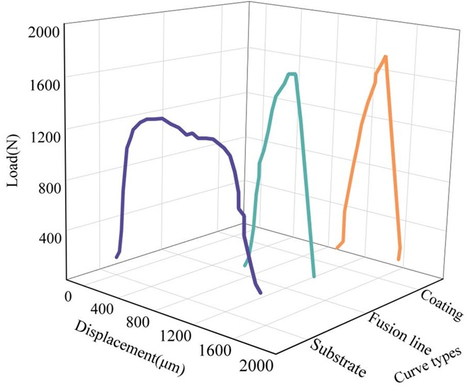
The micro-shear load-displacement curves for the cladding layer, fusion line, and martensitic stainless steel substrate are shown in Figure 7. It can be seen that, compared to the cladding layer and fusion line, the substrate has an extremely long yield stage (approximately 1000 \(\mu\)m), indicating that the martensitic stainless steel substrate has high plasticity.
4.3.2 Wear resistance of cladding layers
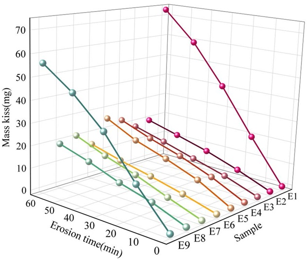
The Martensitic stainless steel substrate used in offshore wind power generation is: (E1) G-X5CrNi13-4, with the following main components: (E2) SF, (E3) SF + 1% CeOz, (E4) SF + 2% CeOz, (E5) SF + 3% CeOz, (E6) SF + 10% Ta, (E7) SF + 20% Ta, (E8) SF + 30% Ta, (E9) SF + 2% CeOz + 20% Ta. To evaluate the erosion resistance of the epoxy resin asphalt coating in a marine environment, this section uses an erosion testing machine to subject the substrate and coating surface of offshore wind power equipment to 90\(\mathrm{{}^\circ}\) and 30\(\mathrm{{}^\circ}\) sand-containing water jet erosion. The specific experimental analysis results are as follows.
1) 90\(\mathrm{{}^\circ}\) erosion wear performance. The erosion weight loss changes of the substrate and the eight component cladding layers at a 90\(\mathrm{{}^\circ}\) erosion angle are shown in Figure 8. The mass loss of the substrate and the eight component cladding layer samples within 60 minutes was significantly smaller than that of the martensitic stainless steel substrate (140.25 mg), with an average mass loss of approximately 20% of the substrate. Additionally, it can be observed that the mass loss curves of all component samples exhibit a continuously decreasing slope, indicating that as the duration of solid-liquid two-phase flow impact increases, the mass loss rate on the sample surface slightly decreases.
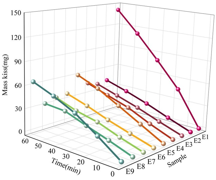
2) 30\(\mathrm{{}^\circ}\) erosion wear performance. The erosion weight loss changes of the substrate and each component cladding layer under a 30\(\mathrm{{}^\circ}\) erosion angle are shown in Figure 9. The phenomenon of wear rate decreasing with increasing erosion time was only observed in the (E1) G-X5CrNi13-4 (substrate) and (E9) SF + 2% CeO\(_2\) + 20% Ta cladding layers, with mass losses of 72.63 mg and 55.83 mg, respectively, within 60 minutes, far exceeding those of other cladding layers. The performance of the remaining cladding layers was relatively better.
In the 90\(\mathrm{{}^\circ}\) abrasion wear test, the abrasion wear resistance of all epoxy resin asphalt coating samples was significantly higher than that of the martensitic stainless steel substrate. In the 90\(\mathrm{{}^\circ}\) abrasion wear test, only the (E1)G-X5CrNi13-4 (substrate) and (E9)SF+2%CeO\(_2\)+20%Ta samples exhibited higher mass loss. Overall, the epoxy resin asphalt paint cladding layers based on laser cladding technology demonstrated excellent erosion wear resistance performance.
5 Conclusion
This paper combines the structural characteristics of offshore wind turbine units with the environmental features of marine tidal ranges to propose a coating system consisting of a “base layer + top layer” for the contact surfaces between the offshore wind turbine foundation caisson and dry-laid stone blocks, and a “base layer + intermediate layer + top layer” coating system for the upper and vertical surfaces.
For the corrosion-resistant coating on the offshore wind turbine foundation, this paper prepares an acrylic polymer as the corrosion-resistant coating for the offshore wind turbine foundation. After testing for impact resistance, pencil hardness, and seawater contact angle, the optimal addition ratio is determined to be 18%.
For the anti-abrasion wear coating of offshore wind turbine foundations, this study employed atmospheric plasma spraying of a WC-12Co composite coating. The metal elements and waste metal elements exhibit varying degrees of diffusion. The Co mass fraction is 18.22%, which strongly promotes the wetting of the WC phase, effectively enhancing the coating’s anti-abrasion wear performance.
Based on the properties of martensitic stainless steel, epoxy resin was selected as the raw material, and laser cladding technology was used to repair the worn areas of the offshore wind turbine substrate. In sand-containing water jet erosion tests, the average mass loss of the cladding layers at a 90\(\mathrm{{}^\circ}\) erosion angle was only approximately 20% of the substrate.